Thursday, September 30, 2010

Pratt & Whitney F100

The Pratt & Whitney F100 is a turbofan jet engine developed by Pratt & Whitney for the US Air Force to power the F-15 Eagle and F-16 Fighting Falcon. Regarded as one of the world's safest fighter engines, the F100 first flew in an F-15 Eagle in 1972 with a thrust of 23,930 lbf. Variants: the F100-100, F100-PW-200, F100-PW-220, and the F100-PW-229, which incorporates modern turbine materials, cooling management techniques, compressor aerodynamics, and electronic controls.

In 1967, the United States Navy and United States Air Force got together to invite bids for the construction of jet engines for the F-15 Eagle and the F-14 Tomcat. The combined program was called Advanced Turbine Engine Gas Generator (ATEGG) with goals to improve thrust and reduce weight to achieve a thrust-to-weight ratio of 9. The program requested proposals and would award Pratt & Whitney a contract in 1970 to produce F100-PW-100 (USAF) and F401-PW-400 (USN) engines.

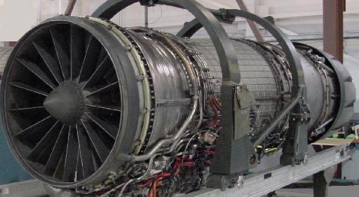
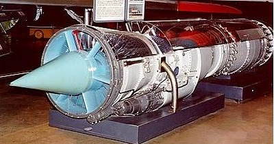
Specifications for the Pratt & Whitney F100

Type: Afterburning turbofan
Dry weight: 3,740 lb
Length: 191 in
Diameter: 46.5 in
Compressor: Dual Spool Axial compressor with 3 fan and 10 compressor stages
Bypass ratio: 0.36:1
Combustors: annular
Turbine: 2 low-pressure and 2 high-pressure stages
Maximum thrust: 17,800 lbf (79.1 kN) military thrust; 29,160 lbf (129.6 kN) with afterburner
Overall pressure ratio: 32:1


Wednesday, September 29, 2010

Pratt & Whitney TF30

The Pratt & Whitney TF30 was turbofan jet engine which was developed by Pratt & Whitney to power the F6D Missileer, the F-111 Aardvaak, the F-14A Tomcat, and the A-7 Corsair II. The first performance of the TF30 took place in 1964 and it was manufactured until 1986.

Before the introduction of the TF30, all supersonic jet aircraft used afterburning turbojet engines as opposed to turbofan engines. A turbojet engine's entire volume of intake air is directed through the engine core, whereas in a turbofan design, a significant percentage of the intake air is routed around the core. Turbofan engines deliver much improved fuel burn efficiencies over turbojets. An afterburning turbofan combines the fuel economy of a turbofan with the greatly increased thrust produced by an afterburner.

Specifications of the Pratt & Whitney TF30

Type: Turbofan
Length: 6.14 m
Diameter: 1.245 m
Dry weight: 1825 kg
Compressor: axial with 6 low pressure and 7 high pressure stages
Combustors: annular
Turbine: 3 stage low pressure turbine, 1 stage high pressure turbine
Bypass ratio: 0.878:1


Tuesday, September 28, 2010

General Electric F110

The General Electric F110 was an axial-flow compressor engine with afterburning turbofan. The F110 was developed in 1985 by General Electric from the F101 engine for the US Air Force and the US navy to power the F-16C Fighting Falcon, F-15K Strike Eagle, and the F-14B Super Tomcat. The GE F110 was developed using the same basic design of the F101; the innovation was that it had a different fan and afterburner packages to improve engine performance.

The GE F110 provided approximately 4,000 lbf (17.8 kN) more thrust than the F100-PW-200 as it required more air, which led to the increase in the area of the engine intake. The F-16C/D Block 30/32s were the first to be built with this larger intake and a common engine bay, able to accept both engines.

Specifications of the General Electric F110-GE-129

Type: Afterburning turbofan engine
Length: 182.3 - 232.3 in (463 - 590 cm)
Diameter: 46.5 in (118 cm)
Dry weight: 3,920 - 4,400 lb (1,778 - 1,996 kg)
Compressor: 9 compressor stages
Combustors: annular
Turbine: 2 low-pressure and 1 high-pressure stages
Maximum thrust: 27,000 - 28,000 lbf (120 - 125 kN)
Overall pressure ratio: 29.9:1 - 30.4:1
Thrust-to-weight ratio: 6.36:1


Monday, September 27, 2010

General Electric J85

The J85 was a single-shaft, axial-flow turbojet engine developed by General Electric for Northrop to power the F-5 Freedom Fighter and the T-38 Talon. It was also used on the A-37 Dragonfly attack aircraft. The GE J85 could produce up to 2,950 lbf (13 kN) of thrust dry, as afterburning variants could reach up to 5,000 lbf (22 kN).

The basic engine design was quite small, about 18 inches (0.46 m) in diameter, and 45 inches long (1.14 m). It was fitted with an eight-stage axial-flow compressor powered by two turbine stages, as it was capable of generating up to 2,950 lbf (13 kN) of dry thrust, or more with an afterburner. At full throttle at sea level, this engine, without afterburner, consumed approximately 400 US gallons (1,520 L) of fuel per hour. At cruise altitude and power, it consumed approximately 100 gallons (380 L) per hour. Several variants of the J85 were produced. The J85-21 variant added a stage ahead of the base 8-stage compressor for a total of 9 stages, improving thrust.

Specifications of the General Electric J85

Type: Turbojet engine
Length: 45.4 inches
Diameter: 17.7 inches
Dry weight: 396 – 421 pounds (depending on accessory equipment installed)
Compressor: 8 stages (9 stages in J85-21)
Combustors: annular
Turbine: 2 stages
Maximum thrust: 2850 – 3100 lbf thrust (dry)
Specific fuel consumption: 0.96 – 0.97
Thrust-to-weight ratio: 7.5 (-21), 6.6 (-5), 6.8 (-13), 7 (-15)


Sunday, September 26, 2010

General Electric J73

The General Electric J73 was an axial-flow turbojet engine made by General Electric to power the F-86H Sabre. It was developed from the GE J47. The J73 was fitted with variable inlet guide vanes, and single-shell combustor case

Specifications of the General Electric J73-GE-5

Type: Turbojet engine
Length: 200 in (5 m)
Diameter: 39.5 in (1 m)
Dry weight: 3,650 lb (1,656 kg)
Compressor: 12 stage, axial flow, variable inlet guide vanes
Combustors: 10 cannular combustion chambers
Turbine: 2 stage
Maximum thrust: 9,500 lbf (42 kN) dry; 12,500 lbf (55.6 kN) with afterburner
Overall pressure ratio: 7.5:1
Specific fuel consumption: 0.9 lb/hr/lbf (dry power)
Thrust-to-weight ratio: 3.4 lbf/lb


Saturday, September 25, 2010

Allison J35

The Allison J35 was an axial-flow turbojet engine which was developed from the GE TG-180. Designed in 1946, the J35 was the first axial-flow compressor engine developed for the US Air Force to power the F-84 Thunderjet and the F-89 Scorpion. It consisted of an eleven-stage axial-flow compressor and a single-stage turbine. The J35 could produce a maximum thrust of 7,400 lbf. Although, it was originally designed by General Electric, the major production was by Allison.

The J35 first flew in the XP-84 in 1946. Late in 1947, complete responsibility for the production of the engine was transferred to the Allison Division of the General Motors Corporation. Some J35s were built by GM's Chevrolet division. More than 14,000 J35s had been built by the time production ended in 1955.

Specifications of the Allison J35

Type: Afterburning turbojet
Models: J35-A-11 (6,000 lb thrust); J35-A-15C (4,000 lb thrust); J35-A-35A (7,400)
Length: 23.8 ft
Diameter: 3.5 ft
Dry weight: 2,850 lb (1,293 kg) including afterburner
Compressor: 11-stage axial compressor
Turbine: Single-stage
Maximum thrust: 7,400 lbf (33 kN) with afterburner
Thrust-to-weight ratio: 2.60 (25.5 N/kg)
Maximum operating altitude: 50,000 ft (15,000 m)
Cost per unit: US$46,000


Friday, September 24, 2010

Pratt & Whitney PW4000

The PW4000 is a two-spool, high-bypass turbofan engine which was developed by Pratt & Whitney to power the Boeing 777 and Airbus A300 aircraft. Based on fan diameter, the PW4000 is divided into 3 distinct families. The PW4000 features advanced technology materials and Full Authority Digital Engine Control (FADEC), for good fuel economy and reliability.

The first family is the 94 inch (2.4 m) diameter fan with certified thrust ranging from 52,000 to 62,000 lbf (230 to 275 kN). It powers the Airbus A310-300 and A300-600 aircraft and Boeing 747-400, 767-200/300 and MD-11 aircraft and is certified for 180-minute ETOPS if used in twinjets. These models include the PW4052, PW4056, PW4060, PW4062, PW4062A, PW4152, PW4156A, PW4156, PW4158, PW4460, and PW4462.

The second family is the 100 inch (2.5 m) diameter fan engine developed specifically for Airbus Industrie's A330 twinjet. It has certified thrust from 64,500 to 68,600 lbf (287 to 305 kN). Models are numbered PW4164, PW4168, and PW4168A. The third family is the 112 inch (2.8 m) diameter fan engine developed specifically for Boeing's 777 where it was the launch engine. It has certified thrust from 86,760 to 99,040 lbf (386 to 441 kN).

Specifications for the Pratt & Whitney PW400-100

Type: Two spool high bypass ratio Turbofan
Length: 163.1 in (4.14 m)
Diameter: 100 in (2.54 m) (fan)
Compressor: 1 stage fan, 5 stage low pressure compressor, 15 stage (5 variable) high pressure compressor
Combustor: Annular
Turbine: 2 stage high pressure turbine, 5 stage low pressure turbine
Maximum thrust: 64,000 - 70,000 lbf (284.7 - 311.4 kN)
Overall pressure ratio: 32.0:1 - 35.4:1
Bypass ratio: 5.0:1

Pratt & Whitney PW4000 on Boeing 777

Thursday, September 23, 2010

General Electric F414

The General Electric F414 is an axial-flow turbofan engine which has been manufactured by General Electric Aviation to power the F/A-18E/F Super Hornet. The F414 was developed from GE F404 as is a low risk derivative. In fact, the F414 engine was originally envisioned as not using any new materials or processes, and was designed to fit in the same footprint as the F404.

The F414 has an axial seven-stage compressor. Its combustor was annular and its turbine consisted of one low-pressure stage and one high-pressure stage. The engine had a maximum thrust of 22,000 lbf (98 kN). The F414 continues to be improved, both through internal GE efforts and federally funded development programs. By 2006, GE tested an Enhanced Durability Engine (EDE) with an advanced core. The EDE engine provided a 15% thrust increase or longer life without the thrust increase. It has a six-stage high-pressure compressor (down from 7 stages in the standard F414) and an advanced high-pressure turbine.

One of the major differences between the F414 and the F404 is the fan section. The fan of the F414 is larger than that of the F404, but smaller than the fan for the F412. The larger fan section increases airflow by 16% and is 5 inches (13 cm) longer. To keep the engine in the F404's footprint, the afterburner section was shortened by 4 in (10 cm) and the combustor shortened by 1 in (2.5 cm). Another change from the F404 is the fact that the first three stages of the high pressure compressor are blisks rather than dovetailed blades, saving 50 pounds (23 kg) in weight.

Specifications for the General Electric F414

Type: afterburning turbofan
Length: 154 in (3,912 mm)
Diameter: 35 in (889 mm)
Dry weight: 1120 kg
Compressor: Axial compressor with 3 fan and 7 compressor stages
Combustors: annular
Turbine: one low-pressure and one high-pressure stage
Maximum thrust: 22,000 lbf (98 kN)
Overall pressure ratio: 30:1
Thrust-to-weight ratio: 9:1

Wednesday, September 22, 2010

Pratt & Whitney J57

The Pratt & Whitney J57 was an axial-flow turbojet engine designed by Leonard S. Hobbs in 1952 and manufactured by Pratt & Whitney to power the B-52 Stratofortress aircraft. The J57 was the first 10,000 lbf (45 kN) thrust class engine in the United States. The J57 company designation was JT3C. This turbojet engine also powered the F-100 Super Sabre and the F-102 Delta Dagger.

Specifications for the Pratt & Whitney J57

Type: Afterburning turbojet
Length: 244 in (6,200 mm)
Diameter: 39 in (1,000 mm)
Dry weight: 5,175 lb (2,347 kg)
Compressor: Two-spool 16-stage axial compressor
Maximum thrust: 11,700 lbf (52.0 kN) dry; 17,200 lbf (76.5 kN) with afterburner
Overall pressure ratio: 11.5:1
Turbine inlet temperature: 1,600 °F (870 °C)
Specific fuel consumption: 2.10 lb/(h·lbf) (214.2 kg/(h·kN)) with afterburner
Thrust-to-weight ratio: 3.32:1 (32.6 N/kg)


Source: Wikipedia

Tuesday, September 21, 2010

General Electric F404

The General Electric F404 was an axial flow, afterburning turbofan engine which was developed by GE to power the F-18 Hornet fighter aircraft. The design of the F404 was based on the YJ101 engine which had been developed for the Northrop YF-17 aircraft. They enlarged the bypass ratio from .20 to .34 to enable higher fuel economy. The engine was designed with a higher priority on reliability than performance. Cost was the main goal in the design of the engine.

The F404 has high resistance to compressor stalls, even at high angles of attack. The reason for this is that it was designed to smooth airflow before it enters the compressor. It requires less than two shop visits per 1,000 flight hours and averages 6,500 hours between in-flight events. The F404 has also shown high responsiveness to control inputs, spooling from idle to full afterburner in 4 seconds. The engine contains an in-flight engine condition monitoring system (IECMS) that monitors for critical malfunctions and keeps track of parts lifetimes.

Specifications for the General Electric F404

Type: Afterburning turbofan
Length: 154 in (3,912 mm)
Diameter: 35 in (889 mm)
Dry weight: 2,282 lb (1,036 kg)
Compressor: axial compressor with 3 fan and 7 compressor stages
Bypass ratio: 0.34:1
Combustors: annular
Turbine: 1 low-pressure and 1 high-pressure stage
Maximum thrust: 11,000 lbf (48.9 kN) military thrust; 17,700 lbf (78.7 kN) with afterburner
Overall pressure ratio: 26:1
Specific fuel consumption: military thrust: 0.81 lb/(lbf·h) (82.6 kg/(kN·h)
Full afterburner: 1.74 lb/(lbf·h) (177.5 kg/(kN·h))
Thrust-to-weight ratio: 7.8:1 (76.0 N/kg)

GE F404 Test Run

Monday, September 20, 2010

Pratt & Whitney F135

The Pratt & Whitney F135 is an afterburning axial-flow turbofan engine which was developed for the F-35 Lightning II fighter aircraft. The F135 is a two-shaft engine which consisted of an axial three-stage low-pressure compressor and a six-stage high pressure compressor. The hot section features an annular combustor with a single-stage high-pressure turbine unit and a two-stage low-pressure turbine. The afterburner features a variable converging-diverging nozzle.

While the conventional and carrier aviation engines, the F135-PW-100 and F135-PW-400, have a maximum (wet) thrust of approximately 43,000 lbf (191 kN) and a dry thrust of approximately 28,000 lbf (125 kN), STOVL variant, F135-PW-600, delivers the same 43,000 lbf (191 kN) of wet thrust as the other types in its conventional configuration. In STOVL configuration, the engine produces 18,000 lbf (80.1 kN) of lift thrust. The STOVL variant engages a clutch to extract around 35,000 shp (26,000 kW) from the LP turbine to turn the forward lift fans, while switching power cycle from mixed (turbofan) to unmixed (turboshaft). Power is transferred forward through shaft to a bevel gearbox, to drive two vertically mounted contra-rotating fans.


The uppermost fan is fitted with variable inlet guide vanes and the fan discharges efflux (low-velocity unheated air) through a nozzle on the underside of the aircraft. This cool air from the lift fan has the added benefit of preventing hot exhaust gases from the core section from being reingested into the engine while hovering. Finally, bypass duct air is sent to a pair of roll post nozzles and the core stream discharges downwards via a thrust vectoring nozzle at the rear of the engine.

Specifications for the Pratt & Whitney F135-PW-100

Type: Afterburning Turbofan engine
Length: 220 in (5.59 m)
Diameter: 51 in (1.29 m)
Dry weight: classified / unpublished
Compressor: Axial 3 stage low-pressure compressor, 6 stage high-pressure compressor
Combustors: Short, annular combustor
Turbine: Single stage high pressure turbine, two stage low pressure turbine
Maximum thrust: 43,000 lbf (191.35 kN) max, 28,000 lbf (124.6 kN) intermediate
Specific fuel consumption: 0.886 lb/(hr*lbf) or 25 g/kNs (w/o afterburner)

Pratt & Whitney F135 Engine

Saturday, September 18, 2010

Pratt & Whitney J58

The Pratt & Whitney J58 (JT11D) was a variable cycle turbojet engine which powered the SR-71 Blackbird reconnaissance aircraft. Basically, the J58 was a hybrid turbojet/ramjet engine, producing 32,000 lbf (142 kN) of thrust. It was the first engine to be able to operate on afterburner for extended periods of time, and the first engine to be flight-qualified by the United States Air Force for Mach 3. A major feature of the J58 was the conical spikes in the variable-geometry inlets, which were automatically moved fore and aft by an Air Inlet Computer.

The spike altered the flow of supersonic air, ensuring subsonic airflow at the engine inlet. The conical spikes are locked in forward position below 30,000 feet. Above that altitude they are unlocked. Above Mach 1.6 airspeed they are retracted approximately 1-5/8 inch (4 cm ) per Mach 0.1, up to total of about 26 inches (66 cm). The J58 was a variable cycle engine which functioned as both a turbojet and a fan-assisted ramjet. Bypass jet engines were rare at the time, but Ben Rich later described the engine as "bypass jet engine by air withdrawal". At Mach 3.2, 80% of the engine's thrust came from the ramjet section, with the turbojet section providing 20%. At lower speeds, the J58 operated as a pure turbojet.

Specifications for the Pratt & Whitney J58

Type: afterburning variable cycle turbojet/ramjet
Length: 17 ft 10 in (an additional 6 in at max. temp.)
Diameter: 4 ft 9 in
Dry weight: approx. 6,000 lb
Compressor: 9-stage, axial flow, single spool
Combustors: 8 can, annular
Turbine: two-stage axial flow
Fuel type: JP-7
Maximum thrust: 34,000 pounds-force (150 kN) (wet), 25,000 pounds-force (110 kN) (dry)
Overall pressure ratio: 6
Specific fuel consumption: 1.9 lb/(lbf-h) (wet), 0.9 lb/(lbf-h) (dry)
Thrust-to-weight ratio: approx. 6
Core air flow: 450 lb/s, (200 kg/s)


Pratt & Whitney J58-p4 on the SR-71

Friday, September 17, 2010

General Electric J47

Designed in March 1946, the General Electric J47 (TG-190) was a turbojet engine developed by General Electric from the J35 engine, and first flew in May 1948. It was used in several types of military aircraft as more than 30,000 units were manufactured. Although production ended in 1956, the GE J47 continued in active service in the US military until 1978, when when the last Boeing KC-97J was retired from service. It was the first axial-flow turbojet approved for commercial use in the United States.

First run on June 21, 1947, the J47 engine was used to power B-47 Stratojet, the B-36 Peacemaker, and the F-86 Sabre. Overhaul life for the J47 ranged from 15 hours, in 1948, to a theoretical 1,200 hours in 1956. The J47-GE-23 was rated to run 225 hours between overhauls. As installed on the F-86F, it experienced one in-flight shutdown every 33,000 hours in 1955 and 1956.

Specifications of the General Electric J47-GE-23

Type: turbojet
Length: 144 inches (3.7 m)
Diameter: 39.5 inches (1.00 m)
Dry weight: 2,707 pounds (1,228 kg)

Performance
Maximum thrust: 5,800 pounds-force (26 kN) at 7950 rpm; 6,500 pounds-force (29 kN) with water injection
Specific fuel consumption: 0.98 lb/hr/lb

Components
Compressor: 12-stage axial compressor
Turbine: Single-stage axial

Thursday, September 16, 2010

Wright J65

The Wright J65 was an axial-flow turbojet engine which powered a number of US Navy and Air Force aircraft. Developed from the Sapphire, the J65 was built by Curtiss-Wright under license from Armstrong Siddeley.

Although it first ran on October 1, 1948, a series of technical problems delayed two years the introduction of the Wright J65. At this point the Pratt & Whitney J57 had already appeared on the market and took many of the J65's potential sales. Nevertheless, once it entered production the J65 proved to be as good as the British versions, and along with the Martin B-57, its original target, the J65 went on to power versions of the A-4 Skyhawk, F-84F Thunderstreak and the two Lockheed XF-104 Starfighter prototypes.

Specifications for the Wright J65

Type: Turbojet
Length: 2,921 m
Diameter: 0,953 m
Dry weight: 1,178 kg

Components
Compressor: axial
Combustors: annular
Turbine: 1 stage

Performance
Thrust: 11,000 lbf
Power-to-weight ratio:

Wednesday, September 15, 2010

General Electric J79

The General Electric J79 was a single-spool turbojet engine which was developed for use in a variety of fighter aircraft. The J79 was produced by General Electric Aircraft Engines in the United States, and under license by several other companies worldwide. There was a simplified civilian version of the GE J79, which was designated the CJ805, powered the Convair 880, while an aft-turbofan derivative, the CJ805-23, powered the Convair 990 airliners and a single Sud Aviation Caravelle intended as a prototype for the US market.

General Electric manufactured more than 17,000 J79 jet engines at a cost of US$ 625,000 per unit. It first run onboard of an aircraft on May 20, 1955, in the B-45 bomber bomb bay. The J79 was lowered from the bomb bay and the four J47s were shut down leaving the B-45 flying on the single J79 for two hours. The J79 was used to power the F-104 Starfighter, B-58 Hustler, F-4 Phantom II, A-5 Vigilante, and the IAI Kfir, enjoying a production run of more than 30 years.

The GE J79 was a single-spool, axial-flow turbojet with a 17-stage compressor with a novel arrangement of variable stator blades which allow the engine to develop pressure similar to a twin-spool engine at a much lower weight. Each blade is made largely of titanium which was not used for large aircraft structures until the 1960s, and each blade today costs several thousand dollars to replace. The turboshaft counterpart to the J79 was the LM1500, used for land and marine applications. Many J79 derived engines have found uses as gas turbines for power plants in remote locations, in applications such as the powering of pipelines.

Specification for the General Electric J79

Type: Afterburning turbojet engine
Compressor: 17-stage axial compressor with variable stator vanes
Diameter: 3.2 ft (1.0 m)Diameter: 3.2 ft (1.0 m)
Length: 17.4 ft (5.3 m)
Dry weight: 3,850 lb (1,750 kg)
Maximum thrust: 11,905 lbf (52.9 kN) dry; 17,835 lbf (79.3 kN) with afterburner Overall pressure ratio: 13.5:1Turbine inlet temperature: 1,210 °F (655 °C)
Specific fuel consumption: 1.965 lb/(h·lbf) (200 kg/(h·kN)) with afterburner

Tuesday, September 14, 2010

General Electric F136

The General Electric F136 is a twin-spool, augmented turbofan jet engine which is being developed by General Electric and Rolls-Royce specifically for the F-35 Lightning II. On July 21, 2004, the F136 began full engine runs at GE's Evendale, Ohio facility. The engine ran for over an hour during two separate runs. In August 2005, the United States Department of Defense awarded the GE and Rolls-Royce team a $2.4 billion contract to develop its F136 engine. The contract was for the system development and demonstration phase of the F136 initiative, scheduled to run until September 2013.

The General Electric and Rolls-Royce Fighter Engine Team successfully completed its Critical Design Review (CDR) for the F136 on February 13, 2008. The F136 successfully completed a high-altitude afterburner testing program at the US Air Force Arnold Engineering Development Center in Tennessee on March 20, 2008, including common exhaust hardware for the F-35 Lightning II aircraft. All test objectives were reached as planned using an engine configured with Conventional Takeoff and Landing (CTOL) and Short Takeoff Vertical Landing (STOVL) common exhaust systems. The engine configuration included a production-size fan and functional augmentor allowing several run periods to full afterburner operation.

The GE Rolls-Royce Fighter Engine Team successfully completed Short Take Off, Vertical Landing (STOVL) testing on an F136 engine at the GE testing facility at Peebles, Ohio on July 16, 2008. The first complete new-build F136 engine began testing January 30, 2009, under the System Development and Demonstration (SDD) contract with the US Government Joint Program Office for the F-35 Joint Strike Fighter program.

Specifications of the General Electric F136

Type: Twin-Spool, Augmented Turbofan Length: 221 in (5.6 m) Diameter: 48 in (1.2 m)
Dry weight: classified
Maximum thrust: 40,000 lbf; 25,000 lbf without afterburner

Components

Compressor: Twin Spool/Counter Rotating/Axial Flow/Low Aspect Ratio Combustors: Annular Combustor Turbine: Axial Flow/Counter-Rotating


General Electric/Rolls Royce F136 Engine (video)

Monday, September 13, 2010

Amblyopia

Amblyopia is loss of visual sharpness in one eye caused by lack of use of that eye in early childhood. It is a disorder of the visual system that is characterized by poor vision in an eye that is otherwise physically normal, or out of proportion to associated structural abnormalities. It has been estimated that amblyopia affects 1–5% of the population in the United States.

Amblyopia is caused by poor transmission of the visual stimulation through the optic nerve to the brain for a sustained period of dysfunction or during early childhood thus resulting in poor or dim vision. Amblyopia normally only affects one eye, but it is possible to be amblyopic in both eyes if both are similarly deprived of a good, clear visual image. Detecting the condition in early childhood increases the chance of successful treatment.

Amblyopia is not an organic problem of the eye. It arises when the part of the visual center, located in the occipital lobe, from the affected eye is not stimulated properly, developing abnormally. This has been confirmed via direct brain examinationThe part of the brain corresponding to the visual system from the affected eye is not stimulated properly, and develops abnormally. This has been confirmed via direct brain examination.

The main treatment involves patching the normal eye to force use of the lazy eye. Sometimes, drops are used to blur the vision of the normal eye instead of putting a patch on it. The underlying condition will also require treatment. If the lazy eye is due to a vision problem (nearsightedness or farsightedness), glasses or contact lenses will be prescribed.

Sunday, September 12, 2010

Hyaloid Artery

The hyaloid artery is the terminal branch of the ophthalmic artery, which, in turn, is a branch of the internal carotid artery. It is contained within the optic stalk of the eye and extends from the optic disc through the vitreous humor to the lens. Usually fully regressed before birth, its purpose is to supply nutrient to the developing lens in the growing fetus.

The hyaloid artery usually regresses during the tenth week of the human embryological development as the lens grows independent of a blood supply. Its proximal portion remains as the central artery of the retina. Regression of the hyaloid artery leaves a clear central zone through the vitreous called the hyaloid canal or Cloquet's canal. Cloquet's canal is named after the man who first described it, French physician Jules Germain Cloquet (1790–1883).

Occasionally the artery may not fully regress, resulting in the condition persistent hyaloid artery. More commonly, small remnants of the artery may remain. Free remnants can sometimes be seen as "floaters". An anterior remnant of the hyaloid artery can be seen in some people as Mittendorf's dot, a small pinpoint-like scar on the posterior surface of the lens. A posterior remnant may be seen where the artery left the optic disc, and is known as Bergmeister's papilla.

Saturday, September 11, 2010

Neuropil

A neuropil, also known as neuropile, is a layer between neuronal cell bodies in the gray matter of the brain and spinal cord. It is composed of a dense tangle of axon terminals, dendrites and glial cell processes. It is where synaptic connections are formed between branches of axons and dendrites.

A neuropil is a complicated spatial network comprising interconnected neuronal processes intermingled with astrocytic glia processes. Synaptic neuropil is the basic constituent of the gray matter of the brain and spinal cord. White matter, which is mostly composed of axons and glial cells, is generally not considered to be a part of the neuropil.

Friday, September 10, 2010

Macular Hole

A macular hole is a breach in the macula, which is an oval-shaped yellow spot near the center of eye retina. A macular hole is caused by a shrinking of the vitreous humour, which is a thick, jellish-like liquid within the eye ball. The macula allow us to see the colors and fine sharp details of objects.

As a person grows older, the vitreous becomes thicker and stringier and begins to pull away from the retina. If the vitreous is firmly attached to the retina when it pulls away, it can tear the retina and create a macular hole. Also, once the vitreous has pulled away from the surface of the retina, some of the fibers can remain on the retinal surface and can contract. This increases tension on the retina and can lead to a macular hole. In either case, the fluid that has replaced the shrunken vitreous can then seep through the hole onto the macula, blurring and distorting central vision.

Thursday, September 9, 2010

Vitreous floaters

Vitreous floaters are tiny deposits of various shape, consistency, refractive index, and motility floating about in the eye's vitreous humour, which is normally transparent. Floaters may be of embryonic origin or acquired due to degenerative changes of the vitreous humour or retina. The perception of floaters is known as myodesopsia, or less commonly as myiodeopsia. Floaters are visible because of the shadows they cast on the retina or their refraction of the light that passes through them, and can appear alone or together with several others in one's field of vision. They may appear as spots, threads, or fragments of cobwebs, which float slowly before the sufferer's eyes. Since these objects exist within the eye itself, they are not optical illusions but are entoptic phenomena.

One specific type of floater is either called Muscae volitantes, or mouches volantes (from the French), which consist of small spots. These are present in most people's eyes and are attributed to minute remnants of embryonic structures in the vitreous humour. Floaters usually follow the rapid motions of the eye, while drifting slowly within the fluid. When they are first noticed, the natural reaction is to attempt to look directly at them. However, attempting to shift one's gaze toward them can be difficult since floaters follow the motion of the eye, remaining to the side of the direction of gaze. Floaters are, in fact, visible only because they do not remain perfectly fixed within the eye.

Vitreous floaters are able to catch and refract light in ways that somewhat blur vision temporarily until the floater moves to a different area. Often they trick the sufferer into thinking they see something out of the corner of their eye that really is not there. Most sufferers, with time, learn to ignore their floaters. For people with severe floaters it is nearly impossible to completely ignore the large masses that constantly stay within almost direct view. Some sufferers have noted a decrease in ability to concentrate while reading, watching television, walking outdoors, and driving, especially when tired.


Wednesday, September 8, 2010

Diabetic Retinopathy

Diabetic retinopathy is progressive damage to the retina of the eye caused by long-term diabetes mellitus, which can eventually lead to blindness. Diabetic retinopathy is an ocular manifestation of systemic disease which affects up to 80% of all patients who have had diabetes for 10 years or more. Despite these intimidating statistics, research indicates that at least 90% of these new cases could be reduced if there was proper and vigilant treatment and monitoring of the eyes.

Nonproliferative diabetic retinopathy develops first as blood vessels in the eye become larger in certain spots. Blood vessels may also become blocked. This may lead to small amounts of retinal bleeding, with fluid leaking into the retina. At first, it may not be very severe. In most cases, it will leave just a few specks of blood, or spots, floating in a person's visual field, though the spots often go away after a few hours.

Proliferative retinopathy is the more advanced and severe form of the disease when new blood vessels start to grow again in the eye. These new vessels are fragile and can bleed. Then, small scars develop on the retina and in the vitreous humour and coroids. AS a result, there is vision loss, as well as other problems.

Tuesday, September 7, 2010

Muller Cells

Muller cells are specialized glial cells that are found in the retina of the human eye. Although they function as any normal glial cells, it has been seen, after an injury to the retina, that Müller cells undergo dedifferentiation into multipotent progenitor cells. At this point, the progenitor cell can divide and differentiate into a number of retinal cell types, including photoreceptor cells, that may have been damaged during injury. Additionally, recently published research has shown that Müller cells act as a light collector in the mammalian eye, analogous to a fiber optic plate, funneling light to the rod and cone cells. Müller cells are currently being studied for their role in neural regeneration, a phenomenon that is not known to occur in humans.

Müller cells are the principal glial cell of the retina. They form architectural support structures stretching radially across the thickness of the retina and are the limits of the retina at the outer and inner limiting membrane respectively. Muller cell bodies sit in the inner nuclear layer and project irregularly thick and thin processes in either direction to the outer limiting membrane and to the inner limiting membrane.

Monday, September 6, 2010

Retinal Artery

The retinal artery (or central retinal artery) is an oxygenated blood vessel which branches off the ophthalmic artery, running inferior to the optic nerve within its dural sheath to the eyeball. After penetrating the optic nerve close to the eyeball, the retinal artery sends branches over the internal surface of the retina. These terminal branches supplied the retina with nutrients and oxigen. However, the fovea and a small area surrounding it are not supplied by the central retinal artery or its branches, but instead by the choroid.

The retinal artery also supplies all the nerve fibers that form the optic nerve that carries the visual information to the occipital lobe cerebral cortex, including those that reach over the fovea. If the central retinal artery gets occluded, there is complete loss of vision in that eye even though the fovea is not affected. The entire retina, with the exception of the fovea, becomes pale and swollen and opaque while the central fovea still appears reddish due to the choroid color that shows through.

Sunday, September 5, 2010

Inner Plexiform Layer

The inner plexiform layer is a layer of the retina which consists of a dense reticulum of fibrils formed by interlaced dendrites of retinal ganglion cells and cells of the inner nuclear layer. Within this reticulum a few branched spongioblasts are sometimes embedded.

Bipolar, amacrine and ganglion cells are linked up and interact in the inner plexiform layer. The axonal endings of bipolar cells bring information from the outer plexiform layer (OPL) to the neuropil of the inner plexiform layer (IPL). Here bipolar cells talk to different varieties of functionally specialized amacrine cells and to dendrites of the various ganglion cells.

Saturday, September 4, 2010

Keratoplasty

Keratoplasty, also known as corneal transplantation, is a surgical procedure where a damaged cornea is replaced by donated corneal tissue (the graft) in its entirety (penetrating keratoplasty) or in part (lamellar keratoplasty). The graft has been removed from a recently deceased individual with no known diseases or other factors that may affect the viability of the donated tissue or the health of the recipient. The cornea is the transparent front part of the eye that covers the iris, pupil and anterior chamber. The surgical procedure is performed by ophthalmologists, medical doctors who specialize in eyes, and is often done on an outpatient basis.

Penetrating keratoplasty

A trephine (a circular cutting device) is then placed over the cornea and is used by the surgeon to cut the host cornea, which removes a circular disc of the patient cornea. The trephine is then removed and the surgeon cuts a circular graft (a "button") from the donor cornea. Once this is done, the surgeon returns to the patient's eye and removes the host cornea.

The donor cornea is then brought into the surgical field and maneuvered into place with forceps. Once in place, the surgeon will fasten the cornea to the eye with a running stitch (as used in the upper image above) or a multiple interrupted stitches (as in the lower image). The surgeon then reforming the anterior chamber with a sterile solution injected by a cannula, then testing that it's watertight by placing a dye on the wound exterior.

Antibiotic eyedrops placed, the eye is patched, and the patient is taken to a recovery area while the effects of the anesthesia wear off. The patient typically goes home following this and sees the doctor the following day for the first post operative appointment.

Thursday, September 2, 2010

Vitrectomy

Vitrectomy is a surgical removal of some or all of the vitreous humor from the eye. It may be performed when there is a retinal detachment, since removing the vitreous gel gives the ophthalmologist better access to the back of the eye. Vitrectomy may also be performed to clear blood and debris from the eye, to remove scar tissue, or to alleviate traction on the retina.

Anterior vitrectomy entails removing small portions of the vitreous from the front structures of the eye - often because these are tangled in an intraocular lens or other structures. Pars plana vitrectomy is a general term for a group of operations accomplished in the deeper part of the eye, all of which involve removing some or all of the vitreous - the eye's clear internal jelly.

Wednesday, September 1, 2010

Diplopia (Double Vision)

Diplopia, also known as double vision, is the simultaneous perception of two images of a single object. These images may be displaced horizontally, vertically, or diagonally in relation to each other. Diplopia has a diverse range of ophthalmologic, infectious, autoimmune, neurological, and neoplastic causes. A key pathological emphasis should be placed upon the Trochlear nerve (fourth cranial nerve) which causes weakness of the superior oblique muscle, resulting in a downward and inward gazing of the eyes.

Diplopia is one of the most troublesome visual disorders a patient can experience. The ability to read, walk and perform common activities is suddenly disrupted. The management of double vision may include prisms, orthoptics, therapy, eye muscle surgery and occlusion.

Binocular diplopia is double vision which occurs as a result of the misalignment of the two eyes relative to each other, such as occurs in esotropia or exotropia. In such a case while the fovea of one eye is directed at the object of regard, the fovea of the other is directed elsewhere, and the image of the object of regard falls on an extra-foveal area of the retina.