Tuesday, November 30, 2010

AN/FPS-108 Cobra Dane

The AN/FPS-108 Cobra Dane was a large L-band, single-faced, phased-array radar which was developed by Raytheon in 1976, during the Cold War. The main function of the AN/FPS-108 was to provide intelligence on Soviet test missiles fired at the Kamchatka peninsula from locations in southwestern Russia. Operating in the 1215-1400 MHz band, the Cobra Dane originally utilized a Control Data Corporation Cyber 74 mainframe computer for data processing. Data from the radar was sent to the North American Aerospace Defense Command (NORAD) at Cheyenne Mountain Operations Center. The radar antenna face of the building measured about 90 feet in diameter and contained some 16,000 elements.

The AN/FPS-108 system provided 120-degree coverage of a 2,000-mile corridor that spanned the eastern Russian peninsula and northern Pacific Ocean. Its digital data and voice communication systems interfaced with the National Air Intelligence Center (NAIC) and the North American Aerospace Defense Command (NORAD). Aside from determining Soviet missile capabilities, Cobra Dane had the dual secondary role of tracking space objects and providing ballistic missile early warning as this L-band radar had a range of 2,000 miles and could track space objects as far as 25,000 miles away. A modernization effort extended the Cobra Dane’s operational life by 15 years and enhanced its performance to meet upgraded mission requirements. The upgrade featured new hardware, including the signal and data processing system, receivers and displays, and a transition to Ada software.


Traveling Wave Tube

A traveling wave tube is an elongated vacuum tube with an electron gun used as a microwave amplifier. A broadband traveling wave tube can have a bandwidth that exceeds an octave, being capable of gains greater than 40 dB. A magnetic containment field around the tube focuses the electrons into a beam, which then passes down the middle of a wire helix that stretches from the RF input to the RF output, the electron beam finally striking a collector at the other end. A directional coupler, which can be either a waveguide or an electromagnetic coil, fed with the low-powered radio signal that is to be amplified, is positioned near the emitter, and induces a current into the helix.

The helix acts as a delay line, in which the RF signal travels at near the same speed along the tube as the electron beam. The electromagnetic field due to the RF signal in the helix interacts with the electron beam, causing bunching of the electrons (an effect called velocity modulation), and the electromagnetic field due to the beam current then induces more current back into the helix (i.e. the current builds up and thus is amplified as it passes down). A second directional coupler, positioned near the collector, receives an amplified version of the input signal from the far end of the helix. An attenuator placed on the helix, usually between the input and output helices, prevents reflected wave from traveling back to the cathode.

The essential principle of operation of a traveling wave tube lies in the interaction between an electron beam and an radio frequency signal. The velocity, v, of an electron beam is given by:


An anode voltage of 5 kV gives an electron velocity of 4.2 x 10*7 mso*-1. The signal would normally travel at c, the velocity of light (3x10*8 ms*-1), which is much faster than any 'reasonable' electron beam (relativistic effects mean that the electron mass actually increases as its velocity approaches c, so that achieving electron velocities approaching c is a complicated business), If, however, the signal can be slowed down to the same velocity as the electron beam, it is possible to obtain amplification of the signal by virtue of its interaction with the beam. This is usually achieved using the helix electrode, which is simply a spiral of wire around the electron beam.


Without the helix, the signal would travel at a velocity c. With the helix, the axial signal velocity is approximately c x (p /2pa) where a, p are shown above, so the signal is slowed by the factor p/2pa. Note that this is independent of signal frequency. The signal travelling along the helix is known as a slow wave, and the helix is referred to as a slow-wave structure, The condition for equal slow-wave and electron-beam velocities is therefore approximately.

Two Cavity Klystron

In the two cavity klystron, the electron beam is injected into a resonant cavity. The electron beam, accelerated by a positive potential, is constrained to travel through a cylindrical drift tube in a straight path by an axial magnetic field. While passing through the first cavity, the electron beam is velocity modulated by the weak RF signal. In the moving frame of the electron beam, the velocity modulation is equivalent to a plasma oscillation. Plasma oscillations are rapid oscillations of the electron density in conducting media such as plasmas or metals. The frequency only depends weakly on the wavelength. So in a quarter of one period of the plasma frequency, the velocity modulation is converted to density modulation, i.e. bunches of electrons. As the bunched electrons enter the second cavity they induce standing waves at the same frequency as the input signal. The signal induced in the second cavity is much stronger than that in the first.

Monday, November 29, 2010

AN/TPS-59

The AN/TPS-59 is a solid-state, three-dimensional, air search radar designed and manufactured by Lockheed Martin for the US Marine Corps. This phased array radar is highly mobile and conceived for long-range aircraft and tactical ballistic missile detection and tracking. The AN/TPS-59 is also the only mobile radar in the world certified to detect tactical ballistic missiles. The US Marine Corps currently employs AN/TPS-59 Version 3, which can precisely predict missile launch and impact points, and cue defensive weapons against incoming threats. The radar’s 740-kilometer (400 nautical miles) range exceeds the range of 90 percent of the tactical ballistic missiles in the world today, and its mobility allows it to be forward-based to further extend the range of the system.

The AN/TPS-59 Version 3 can be integrated with other sensors for improved launch and impact point prediction, extended range capabilities, cooperative engagement and joint tactical information distribution. With over 126 radars deployed in 17 countries worldwide, the TPS-59/FPS-117 family of solid-state radars has an unsurpassed record for performance and reliability. Similar to the AN/FPS-117, the AN/TPS-59 is used by the United States Marine Corps, Egypt, and Bahrain. It has seen action in Operation Desert Storm, Operation Iraqi Freedom, Operation Enduring Freedom, and has been deployed to the Republic of Korea.

Specifications for the AN/TPS-59

Type: three-dimensional phased array radar
Primary function: air search radar
Maximum range: 400 km
Maximum detection altitude: 90,000 ft (27,000 m)
Weight: 20,000 kg
Primary User: United States Marine Corps
Unit Cost Approx: $50 Million USD
Introduced: in the 1980s


AN/FPS-117

The AN/FPS-117 is a long-range solid-state radar developed by Lockheed Martin. This 3-dimensional air search radar offers superior performance even in high-clutter environments thanks to its state-of-the-art solid-state design and L-band operation. Designed to operate on twenty frequencies channels up to 1400 MHz, the AN/FPS-117 features an advanced pencil beam architecture which provides exceptional detection and tracking as well as outstanding adaptability to changing environmental conditions.

The AN/FPS-117 also provides both air surveillance and en route air traffic control. More AN/FPS-117 systems are in operation today than all other competitive radars combined, assuring worldwide support as they have a low maintainance and personnel costs. The AN/FPS-117 radar is in use as part of the American-Canadian North Warning System and is in operation in several other countries including Australia, Belgium, Brazil, Croatia, Denmark, Estonia, Germany, Hungary, etc. In 1999 the AN/FPS-117 Radar completed a major Modification, to include replacement of the Beacon Radar portion of the system and upgrades to the remote operations of the unmanned sites.


AN/FPS-120

The AN/FPS-120 is a solid state, phased-array radar developed by Raytheon. Computers are used to control the radar and process the data it receives. Vital communications are also maintained through a number of systems. The AN/FPS-120 detects objects as far out as 2,800 nautical miles and can look over a 240-degree sweep, also being able to detect, at an extreme range, objects the size of a small car. Also called the SSPAR, the newly completed AN/FPS-120 was activated on February 1, 2001, after the deactivation of the Clear Air Station's mechanical BMEWS radar. Since then, performance of the upgraded AN/FPS-120 system has been exceptional, with over 99-percent availability, a substantial factor in the cost reduction.

The AN/FPS-120 radar is housed in a triangular-shaped 11 story building on site. The steel frame building that houses two approximately 90' diameter radar array faces on exterior walls and all related equipment. Together they form a coverage area 240 degrees wide and 3,000 miles deep into space. The coverage extends from the Arctic Ocean all the way to the West Coast of the lower 48 states. The upgrade program implemented by Raytheon has enhanced the performance of all three systems, while significantly reducing their operation and maintenance costs.

Sunday, November 28, 2010

AN/TPS-77

The AN/TPS-77 is a solid-state, 3-D long-range surveillance radar developed by Lockheed Martin for the US Armed Forces. With a 360-degree azimuth coverage, the AN/TPS-77 provides superior long-range detection, especially in bad weather conditions and clutter. It can operate 24 hours a day, even with no on-site personnel. Simplified logistics and remote maintenance-monitoring capabilities reduce contribute to low cost of ownership. The AN/TPS-77 also provides accurate target data at ranges up to 250 nautical miles and elevations up to 100,000 feet.

The AN/TPS-77 is a tactical transportable radar system which has the same proven features of its sister products, the AN/TPS-59(V)3 and the AN/FPS-117. It also offers solid-state, active phased array; superior performing L-band operation; modular, commercial-off-the-shelf components; advanced pencil-beam architecture; simplified maintenance.


Saturday, November 27, 2010

AN/MSQ-39

The AN/MSQ-39 Bomb Scoring Radar was a band automatic tracking radar developed in India between 1970 and 1973. It operated in the 8500 to 9600 MHz frequency range. Rather than using a parabolic dish, the AN/MSQ-39 was fitted with an 8 ft diameter fresnel lens. The lens provided improved low-level tracking of aircraft. Ground clutter, meaning returns caused by abnormalities in the earth's terrain or trees, did not affect a radar with a lens as bad as a radar with a parabolic dish. The "39" was a descendent of the M-33 system and a "cousin" to the MPQ-T2 India band.

Friday, November 26, 2010

AN/TPQ-37 Firefinder

The AN/TPQ-37 Firefinder is an electronically-steered, phased array radar which was developed by Raytheon. The radar scans a 90-degree sector for incoming rocket, artillery and mortar fire. Upon detecting a possible incoming round, the system verifies the contact before initiating a track sequence, continuing to search for new targets. The AN/TPQ is an S-band, 15-frequency, long-range radar which can locate ten weapons simultaneously and perform high-burst, datum-plane, and impact registrations. Thanks to its phased array antenna, the Firefinder radar can electronically switch beam positions, thus enabling it to search for new targets while simultaneously tracking previously detected targets.

The AN/TPQ-37 is also capable of first round detection at ranges of 3 to 50 km, dependening on the weapon type. A computer program analyzes the track data and then extrapolates the round’s point of origin. This calculated point of origin is then reported to the operator with map coordinates. Then, system directs effective counterfire against the hostile weapon.

The AN/TPQ-37 RMI (Reliability, Maintainability, Improvement) is an upgraded version of the Firefinder radar which will provide significant improvements over the current AN/TPQ-37 fielded system by providing new, state-of-the-art electronics including an air-cooled modular transmitter and a new radar processor. This new version will also extend the system service life of the AN/TPQ-37 radar and significantly reduce customer life cycle costs, allowing the system to remain the mainstay of long range artillery well into the 21st Century.

Specifications

Type: mobile phased array radar
Maximum range: 50 km
Azimuth sector: 1600 mils (90 degrees)
Prime power: 115/200 VAC, 400 Hz, 3-phase, 43 kW
Peak transmitted power: 120 kW, min.
Permanent storage for 99 targets
Field exercise mode
Digital data interface

Thursday, November 25, 2010

AMSAR

AMSAR is an Active Electronically Scanned Array radar, which has just been developed by the British/French/German GTDAR consortium. "AMSAR" is the acronym for Airborne Multirole Solid State Active Array Radar. It consists of a fixed antenna and up to 2,000 gallium arsenide, monolithic microwave integrated circuit transceiver modules which provides independent control of phase and amplitude and a multibeam capability. The level of beam agility features simultaneous air-to-air, air-to-ground, terrain following and terrain avoidance operating modes. AMSAR also provides multiple jammer nulling, stealthy functionality, low probability-of-intercept (low sidelobes), multistatic operation and a wide bandwidth.

The AMSAR project began in 1993 in a 50/50 Anglo-French programme with German technical participation. The radar is envisaged as a replacement for the Typhoon's CAPTOR radar and the Rafale's RBE2 passive electronically-scanned-array.

Wednesday, November 24, 2010

Klystron

A klystron is a linear-beam vacuum tube which is used as a powerful microwave amplifier which produces both low-power reference signals for superheterodyne radar receivers. It also generates high-power carrier waves for communications and the driving force for modern particle accelerators. Klystron amplifiers coherently amplify a reference signal so its output may be precisely controlled in amplitude, frequency and phase. Many klystrons have a waveguide for coupling microwave energy into and out of the device, although it is also quite common for lower power and lower frequency klystrons to use coaxial couplings instead. In some cases a coupling probe is used to couple the microwave energy from a klystron into a separate external waveguide. All modern klystrons are amplifiers, since reflex klystrons, which were used as oscillators in the past, have been surpassed by alternative technologies.

A klystron amplifies RF signals by converting the kinetic energy in a DC electron beam into radio frequency power. A beam of electrons is produced by a thermionic cathode (a heated pellet of low work function material), and accelerated by high-voltage electrodes (typically in the tens of kilovolts). This beam is then passed through an input cavity. RF energy is fed into the input cavity at, or near, its natural frequency to produce a voltage which acts on the electron beam. The electric field causes the electrons to bunch: electrons that pass through during an opposing electric field are accelerated and later electrons are slowed, causing the previously continuous electron beam to form bunches at the input frequency. To reinforce the bunching, a klystron may contain additional "buncher" cavities. The RF current carried by the beam will produce an RF magnetic field, and this will in turn excite a voltage across the gap of subsequent resonant cavities. In the output cavity, the developed RF energy is coupled out. The spent electron beam, with reduced energy, is captured in a collector.

Erieye radar

The Erieye is an active, pulse-Doppler, S-band radar which has a range of 400 km. Designed by the Swedish firm Ericsson Microwave Systems, the Erieye is used onboard the Saab 2000, Saab and the Brazilian Embraer E-99. The Erieye radar is equipped with a fixed electronically scanned antenna, which is mounted on the fuselage, providing superior resolution over rotodome radars. Erieye radar can detect and track air and sea targets out there on the very distant horizon, and sometimes beyond this due to anomalous propagation. Typical detection range against fighter-sized targets is approximately 425 km, in a 150° broadside sector, both sides of the aircraft. Outside these sectors, performance is reduced in forward and aft directions.

The Erieye radar is fitted with 200 two-way transmit/receive modules that combine to produce a pencil beam, steered as required within the operating 150° sector each side of the aircraft (one side at a time). It is understood that Erieye has some ability to detect aircraft in the 30° sectors fore and aft of the aircraft heading, but has no track capability in this sector. The Erieye also features adaptive waveform generation (including digital, phase-coded pulse compression); Signal processing and target tracking; Track While Scan (TWS); Low sidelobe values (throughout the system's angular coverage); Low- and medium-pulse repetition frequency operating modes; Frequency agility; Air-to-air and sea surveillance modes; and Target radar cross-section display. Today, the Erieye is manufactured by the firm Saab Microwave Systems.


Tuesday, November 23, 2010

AN/APN-241

The AN/APN-241 is a synthetic-aperture radar designed to allow pilots to focus on the mission rather than working the radar. It is the only radar with a 10nm range Windshear mode and its unique two-bar can technology eliminates false alarms. Automatic tilt and gain adjustments of the AN/APN-241 reduce operator tasking, and with simultaneous mode interleaving, crews can select independent radar modes according to mission requirements. The AN/APN-241 provides overlays of flight plan or TCAS information on weather or ground maps for greater situational awareness. Operators may also 'freeze' the AN/APN-241 into a non-emitting mode to gain a tactical advantage.
 
The AN/APN-241 windshear mode is not restricted by altitude. At 20 nautical miles, the AN/APN-241 provides the longest range air-to-air situational awareness mode of any transport radar. The Skin Paint mode also features computer generated target-sizing, a clutterfree display, and hands-free operation to the crew. The highly adaptable AN/APN-241 is currently fielded on four aircraft: C-130H, C-130J, C-27J and C-295. Northrop Grumman has integrated the AN/APN-241 with five different avionics architectures and two antenna systems. As the baseline radar for the LMCO C-130J and Alenia C-27J, it has a solid, long-term production base with logistics and maintenance support through 2030 and beyond.

Monday, November 22, 2010

AN/FPS-126 (PAVE PAWS)

The AN/FPS-126 is a solid-state, space tracking, phased array radar which belongs to the US Air Force Space Command PAVE PAWS radar system. This system is under the control of three 21st Space Wing squadrons for missile warning and space surveillance. The AN/FPS-126 operates at a frequency of 420 to 450 MHz and has the ability to track thousands of satellites orbiting the earth. Developed by Raytheon in the 1980s, the PAVE PAWS radar system is used mainly to detect and track sea-launched (SLBM) and intercontinental ballistic missiles (ICBMs). The radar system is capable of detecting and monitoring a great number of targets that would be consistent with a massive SLBM attack. The system must rapidly discriminate between vehicle types, calculating their launch and impact points in addition to the scheduling, data processing and communications requirements. The operation is entirely automatic, requiring people only for monitoring, maintenance and as a final check of the validity of warnings. Three different computers communicate with each other from the heart of the system, which relays the information to Cheyenne Mountain AS.

The AN/FPS-126 phased array antenna beam steering is done rapidly by electronically controlling the timing (the phase) of the incoming and outgoing signals. Controlling the phase through the many segments of the antenna system allows the beam to be quickly projected in different directions. This greatly reduces the time necessary to change the beam direction from one point to another, allowing almost simultaneous tracking of multiple targets while maintaining the surveillance responsibility. This ability is known as "track while scan". The large fixed antenna array through its better beam focusing, improves system sensitivity and tracking accuracy. A phased array antenna receives signals from space only in the direction in which the beam is aimed. The maximum practical deflection on either side of antenna center of the phased array beam is 60 degrees. This limits the coverage from a single antenna face to 120 degrees. To provide surveillance across the horizon, the building housing the entire system and supporting the antenna arrays is constructed in the shape of a triangle. The two building faces supporting the arrays, each covering 120 degrees, will monitor 240 degrees of azimuth. The array faces are also tilted back 20 degrees to allow for an elevations deflection from three to 85 degrees above horizontal.


Sunday, November 21, 2010

AN/FPS-129 (Globus II)

Also called Globus II, the AN/FPS-129 HAVE STARE is an X-band (10 GHz), narrow beam tracking radar, which is used by the Norwegian Intelligence Service. The AN/FPS-129 has a transmitter power output of 200 Kw and is able to see objects far away, since the combination of the antenna and a relatively high frequency gives a concentrated narrow antenna beam, that makes it possible for the energy to be used with maximum effect. Located at Vardø, Norway, the Globus II has a mechanically steered, parabolic reflector antenna of center-feed type, 27 meters in diameter and housed in a 35-meter diameter radome.

Aside from watching space, the AN/FPS-129 has two main tasks: 1) to gather metric data from satellites, which is used by the US Space Command to produce and maintain the Space Catalog that contains orbit data on all man-made objects in outer space; 2) to create high-resolution radar imagery by selected objects in space. Globus-II can observe satellites in geosynchronous orbit at ranges of some 40,000 kilometers from where the radar is deployed. Thus, the Globus II contributes to the US Space Surveillance Network (SSN), filling a gap in the space surveillance coverage. Data acquired by AN/FPS-129 also contributes to the orbital database maintained by the US Space Command. Information from this database is made publicly available by NASA via the Internet.


Saturday, November 20, 2010

AN/SPG-59

Entering service in 1963, the AN/SPG-59 was a search and illumination radar that was briefly used by the US Navy in the Typhon missile system, during the Cold War. It had a range of 110 nautical miles and an azimuth of 360º. It could search, track, and guide. The AN/SPG-59 had a wide-band receiver which forwarded its received signals back to the ship. Then, ship's computers calculated the interception coarse and forwarded it back to the missile from an omni-directional antenna. This was similar to the older command guidance system, but avoided the inaccuracies of that system by locating the receiver on the missile, which was closer to the target and therefore saw a stronger signal.

The development of the Typhon/SPG-59 system began as a response to the introduction of sea-skimming anti-ship missiles into service with Soviet Naval Aviation groups. First-generation missile systems like Talos and Terrier used a combination of beam riding and semi-active radar homing (SARH) that required a special targeting radar to illuminate the target through the entire interception. Typical installations included either two or four such illumination radars, which limited the number of simultaneous interceptions. Facing volleys of missiles such systems could easily be overwhelmed. Although adding additional radars was possible, it was difficult to arrange as the radars were large and required a clear view of the sky, thus limiting the number of suitable locations. The AN/SPG-59 avoided this problem by acting as both the search and illumination radar. That reduced the problem of siting, as there needed to be only one radar on the ship, albeit a very large one.

Friday, November 19, 2010

AN/APQ-174

The AN/APQ-174 is a multi-mode, Ku band radar designed and manufactured by Raytheon. Developed in the late 1980s from the AN/APQ-168, the AN/APQ-174 is used on the US Army AH-60 Apache, CH-47 Chinook, and other military helicopters. The radar can be used for a variety of missions, which include combat search and rescue and special forces insertion and extraction. The AN/APQ-174 provides terrain following and terrain avoidance for a wide variety of military aircraft. It allows safe flight down to a 100-ft set clearance at night, in adverse weather, and in high-threat environments, lowering the probability of detection by enemy forces and increases mission success through terrain masking and minimizing time spent in threat range. The modes of the AN/APQ-174 include ground mapping, air-to-ground ranging, terrain following, weather detection, terrain avoidance, cross scan modes (TF/TA, TF/GM, TF/WX, TF/BCN), beacon interrogation, and low power/low velocity.

Thursday, November 18, 2010

AN/APQ-186

The AN/APQ-186 is a multi-mode radar designed and manufactured by Raytheon to be used on several types of transport and combat helicopters. The AN/APQ-186 was developed from the AN/APQ-174, which is a Ku band radar used on military helicopters for navigation. Using the AN/APQ-186, the pilot can fly a low levels down to a 100-ft set clearance at night, in adverse weather, and in high-threat environments. This radar also lowers the probability of detection by enemy forces and increases mission success through terrain masking and minimizing time spent in threat range. It reduces risk to the aircrew and the aircraft by balancing the low-level terrain clearance altitude with flight safety considerations. The AN/APQ-186 uses proven control algorithms, high-reliability designs, and extensive built-in-test software to provide a high-confidence system with high user acceptability.

Wednesday, November 17, 2010

AN/SPG-55

The AN/SPG-55 was a naval, ship-based fire-control radar developed by the firm Sperry Corporation for the US Navy. The AN/SPG-55 served as the guiding radar for the RIM-67 and RIM-2 Terrier surface-to-air missiles. It functioned in the frecuency range between 5.4 and 5.9 GHz, and, if the need arose, it could also be used as an improvised search radar. The AN/SPG-55 was used on board the Belknap-class cruisers, the Farragut class destroyers, the Kitty Hawk-class aircraft carriers, and Leahy-class cruisers. The Sperry Corporation and the Radio Corporation of America manufactured the following versions: the AN/SPG-55, which was the original model; the AN/SPG-55A, which could also guide semi-active guided missiles; the AN/SPG-55B, which supported beam-riding and homing Terrier missiles as well as newer standard missiles.


Tuesday, November 16, 2010

Monica Tail Warning Radar

Monica tail warning radar, or ARI 5664, was an aircraft radar used by the RAF during the Second World War. It was mounted in the tail of bombers from 1942. The Monica functioned at frequencies of around 300 MHz. It was developed at the Bomber Support Development Unit in Worcestershire. Nevertheless, the Germans designed and manufactured a passive radar detector, known as the Flensburg (FuG 227), which was used by Luftwaffe nightfighters from Spring 1944 onward to home in on bombers using Monica. However, Monica-equipped aircraft did not suffer an increased casualty rate overall. The Monica tail warning radar was also used by the US Army Air Corps as the AN/APS-13, where it was also used as the radar altimeter for the Little Boy atomic bomb.

Flensburg Radar Detector (FuG 227)

The Flensburg, or FuG 227, was a World War II passive radar detector developed by Siemens AG and used by the Luftwaffe from Spring 1944. The FuG 227 used wing-mounted dipole antennae and was sensitive to frequencies of 170-220 MHz. It allowed Luftwaffe nightfighters to home in on the Monica tail warning radar fitted to RAF bombers. On July 13, 1944, a Junkers Ju 88G-1 nightfighter equipped with a Flensburg radar detector mistakenly landed at RAF Woodbridge. After examining the Flensburg, the RAF ordered Monica to be withdrawn from all RAF Bomber Command aircraft. Subsequently, further variants of Flensburg (Flensburg II to Flensburg VI) were developed for detecting Allied radar jammers. Only Flensburg II and III were used operationally.

Monday, November 15, 2010

AN/APG-79

The AN/APG-79 is an active electronically array radar which was developed by Raytheon Company to be used by the US Navy aboard the F/A-18E/F Super Hornet and EA-18G Growler aircraft. The APG-79 is fitted out with transmit/receive (TR) modules populated with GaAs MMICs. The beam of the AN/APG-79 renders nearly instantaneous track updates and multi-target tracking capability. To make maintenance easier, this radar is installed in a slide-out nose rack of the aircraft. The APG-79 is equipped with an entirely solid-state antenna construction, which improves reliability and lowers the cost compared to a traditional system. The radome of the APG-79 for the F/A-18E/F slides forward instead of hinging to the right, which saves space in aircraft carrier hangars. This aircraft-based radar is compatible with current F/A-18 weapon loads and enables aircrew to fire the AIM-120 AMRAAM, simultaneously guiding several missiles to several targets widely spaced in azimuth, elevation or range.

With its active electronic beam scanning — which allows the radar beam to be steered at nearly the speed of light — the APG-79 optimizes situational awareness and provides superior air-to-air and air-to-ground capability. The agile beam enables the radar’s air-to-air and air-to-ground modes to interleave in near-real time, so that pilot and crew can use both modes simultaneously, an unprecedented technological leap. The APG-79 demonstrates reliability, image resolution, and targeting and tracking range significantly greater than that of the current F/A-18 radar. With its open systems architecture and compact, commercial-off-the-shelf (COTS) parts, it delivers dramatically increased capability in a smaller, lighter package. The array is composed of numerous solid-state transmit and receive modules to virtually eliminate mechanical breakdown.

The APG-79 radar completed formal operational evaluation testing in December 2006. As of January 2007 the radar was installed in 28 aircraft; some were experiencing software problems but that issue was expected to be resolved by the end of fiscal year 2007. As of July 2008, Raytheon had delivered 100 APG-79 sets to the Navy; on June 3, 2008, the Navy received the first APG-79-equipped EA-18G Growler. The Navy expects to order approximately 400 production radars.


Sunday, November 14, 2010

Continuous Wave Radar

A continuous wave radar is a radar system in which a continuous wave radio energy is transmitted and then received from any reflecting objects. The return frequencies are shifted away from the transmitted frequency based on the Doppler effect if the objects are moving. A continuous wave radar continually transmits energy in the direction of the target and receives back reflection of the continuous wave, providing velocity information by comparing the differences in the transmitted and received waves and making use of the Doppler effect.

The armed forces use continuous wave radars to guide semi-active radar homing (SARH) air-to-air missiles, such as the U.S. AIM-7 Sparrow. The launch aircraft illuminates the target with continuous wave radar signals, and the missile homes in on the reflected radar waves. Since the missile is moving at high velocities relative to the aircraft, there is almost always a strong return. Most modern air combat radars, even pulse Doppler sets, have a CW function for missile guidance purposes.

The advantage of using a continuous wave radar is that it has no minimum or maximum range and maximize power on a target because it is always broadcasting. However, it also has the disadvantage of only detecting moving targets, as stationary targets (along the line of sight) will not cause a Doppler shift and the reflected signals will be filtered out. CW radar systems are used at both ends of the range spectrum, as radio-altimeters at the close-range end (where the range may be a few feet), and early warning radars at long range.

Saturday, November 13, 2010

Bistatic Radar

A bistatic radar is a radar system composed of a transmitter and a receiver, set apart at a distance which is comparable to the expected target distance. In other words, a bistatic radar consists of separately located transmitting and receiving sites. The transmitter and receiver share a common antenna, which is called a monostatic radar system. In some configurations, bistatic radars are designed to operate in a fence-like configuration, detecting targets which pass between the transmitter and receiver, with the bistatic angle near 180 degrees. This is a special case of bistatic radar, known as a forward scatter radar, after the mechanism by which the transmitted energy is scattered by the target. In forward scatter, the scattering can be modeled using Babinet's principle and is a potential countermeasure to stealth aircraft as the radar cross section (RCS) is determined solely by the silhouette of the aircraft seen by the transmitter, and is unaffected by stealth coatings or shapings.

the bistatic radar is mainly used for weather radar and its technology has been in use for several years at the Institute of Atmospheric Physics at the German Aerospace Center.This system is also of some importance in militar applications. The so called "semi-active" missile control system, as used in the missile unit "HAWK", is practically a bistatic radar. By receiving the side lobes of the transmitting radars direct beam, the receiving sites radar can be synchronized. If the main lobe is detected, an azimuth information can be calculated also. A number of specialized bistatic systems are in use, for example, where multiple receiving sites are used to correlate target position.

A multistatic radar system is one in which there are at least three components - for example, one receiver and two transmitters, or two receivers and one transmitter, or multiple receivers and multiple transmitters. It is a generalisation of the bistatic radar system, with one or more receivers processing returns from one or more geographically separated transmitters.


Friday, November 12, 2010

AN/SPG-49

The AN/SPG-49 was a naval fire-control radar developed between 1947 and 1948 by the American firm Sperry Corporation for the US Navy. The AN/SPG-49 was a target illumination and tracking radar which was used along the AN/SPW-2 in the guidance system of the RIM-8 surface-to-air missile. It was designed in 1947 and its development was parallel to that of the RIM-8. The fire control of the AN/SPG-49 had a frecuency range from 5.4 to 5.9 GHz. Since this system was cumbersome and heavy, the AN/SPG-49 was replaced by the AN/SPQ-5 radar from 1979.

Thursday, November 11, 2010

Fire-control Radar

The fire-control radar is a radar that continuously provides information about the target position, such as elevation, azimuth, range, and velocity. These data are simultaneously fed into a fire-control system to calculate the information on how to direct weapons so that they hit the target. A fire-control radar features a very high pulse repetition frequency (prf), a very narrow pulse width, and a very narrow beam width. In other words, this type of radar emits a narrow, intense beam of radio waves to ensure accurate tracking information and to minimize the chance of losing track of the target. A fire-control radar must be directed to the general location of the desired target because of the narrow-beam pattern.
 
Some modern fire-control radars have a track-while-scan capability which enables it to function simultaneously as a fire-control radar and a search radar. This works either by having the radar switch between sweeping the search sector and sending directed pulses at the target to be tracked, or by using a phased-array antenna to generate two or more discrete radar beams and dividing them between both tasks.

A fire-control radar functions in three phases: 1) designation phase, in which the fire-control radar must be directed to the general location of the target due to the radar’s narrow beam width, ending when lock-on is acquired; 2) acquisition phase, in which the fire-control radar searches in the designated area in a predetermined search pattern until the target is located or redesignated; 3) tracking phase, in which the radar system locks onto the target, ending when the target is destroyed.

The efficiency of a fire-control radar is determined by primarily by two factors, radar resolution and atmospheric conditions. Radar resolution is the ability of the radar to differentiate between two targets closely located. The first, and most problematic, is gaining high range resolution. To do this in a basic fire-control radar system, it must operate at a high pulse repetition frequency and have a high receiver sensitivity. Bearing resolution is typically ensured by using a narrow beam width. Atmospheric conditions, such as moisture lapse, temperature inversion, and dust particles also affect radar performance. Moisture lapse and temperature inversion often cause ducting, in which RF energy is bent as it passes through hot and cold layers. This can either extend or reduce the radar horizon, depending on which way the RF is bent. Dust particles and water droplets cause attenuation of the RF energy, translating into a loss of effective range.


Wednesday, November 10, 2010

SCR-584 Radar

The SCR-584 was a microwave radar which was designed and manufactured by the MIT Radiation Laboratory during World War II. Extremely advanced for the time it was introduced, the SCR-584 could achieve high accuracy using a conical scanning system, in which the beam is rotated around the antenna's axis to find the maximum signal point, thus indicating which direction the antenna should move in order to point directly at the target. This system was not new, having been introduced on the German Würzburg radar in 1941. Nevertheless, the designers of the SCR-584 developed the system much further, adding an automatic tracking mode. Once the target had been detected and was within range, the system would keep the radar pointed at the target automatically, driven by motors mounted in the antenna's base. "SCR-584" stood for "Signal Corps Radio #584".

The SCR-584 was first used in combat at Anzio in February 1944, where it played a key role in breaking up the Luftwaffe's concentrated air attacks on the confined beachhead. The SCR-584 was no stranger to the front, where it followed the troops, being used to direct aircraft, locate enemy vehicles, and track the trajectories of artillery shells, both to adjust the ballistic tables for the 90 millimeter guns, and to pinpoint the location of German batteries for counter-battery fire. The SCR-584 was not, however, used in the rapidly-shifting very front lines, where lighter, less accurate, radars such as the AN/TPS-1 were used. The SCR-584 replaced the earlier and much more complex SCR-270 as the US Army's primary anti-aircraft gun laying system as quickly as they could be produced. In service it proved to be an outstanding system, much more advanced than any other battlefield radar system deployed during the war.


Tuesday, November 9, 2010

AN/APG-82 Radar

The AN/APG-82 is a multi-mode aircraft radar developed by Raytheon for the US Air force's F-15E Strike Eagle. The AN/APG-82 is able to detect and track aircraft and small high-speed targets at distances beyond visual range down to close range, and at altitudes down to treetop level. The APG-82 is an active electronically scanned array (AESA) radar system which emproves the F-15E’s multirole mission capability. In addition to its extended range and improved multi-target track and precision engagement capabilities, the APG-82(V)1 offers a more than twentyfold improvement in system reliability over the legacy F-15E APG-70 radar. This phenomenal level of reliability and maintainability will result in significant maintenance cost savings for the U.S. Air Force.

Fighter aircraft fitted with the APG-82(V)1 AESA radar can simultaneously detect, identify and track multiple air and surface targets at longer ranges than ever before. The longer standoff range facilitates persistent target observation and information sharing for informed decision making. This superior battlespace awareness supports greater tactical mission capability. The result: greatly increased aircraft-aircrew effectiveness and survivability. In November 2007, Raytheon’s AESA radar was competitively selected for the F-15E radar modernization program. Our AESAs are also the radar of choice for the F-15C, F/A-18E/F and EA-18G aircraft.


Sunday, November 7, 2010

Continuous Wave Illuminator

A continuous wave illuminator is a narrowly focused radar beam whose reflected signal is used to obtain a missile lock-on. The continuous wave illuminator is emitted by fire-control radars mounted in fighter aircraft. This intense beam of continuous radio waves is used to ensure accurate tracking information and to minimise the chance of losing track of the target.

Saturday, November 6, 2010

AN/APG-80

The AN/APG-80 is a synthetic aperture radar (SAR) system designed to perform continuous search and to track multiple targets within the forward hemisphere of the aircraft. Developed and manufactured by Northrop Grumman for use on the F-16 Fighting Falcon fighter aircraft, the AN/APG-80 is an agile beam fire control radar which include much greater detection range, high-resolution synthetic aperture radar imagery, and a two-fold increase in reliability compared to conventional, mechanically scanned radars. It is sometimes referred to as an active electronically scanned array system. It became operational in 2003.

The AN/APG-80 can perform air-to-air, search-and-track, air-to-ground targeting and aircraft terrain-following functions simultaneously and for multiple targets. As a SAR system utilizing NG's fourth-generation transmitter/receiver technologies, it has a higher reliability and twice the range of older, mechanically-scanned AN/APG-68 radar systems.


Monopulse Radar

A monopulse radar is similar in general construction to conical scanning systems, but introduces one more feature. Instead of broadcasting the signal out of the antenna "as is", they split the beam into parts and then send the two signals out of the antenna in slightly different directions. When the reflected signals are received they are amplified separately and compared to each other, indicating which direction has a stronger return, and thus the general direction of the target relative to the boresight. Since this comparison is carried out during one pulse, which is typically a few microseconds, changes in target position or heading will have no effect on the comparison.

Making such a comparison requires that different parts of the beam be distinguished from each other. Normally this is achieved by splitting the pulse into two parts and polarizing each one separately before sending it to a set of slightly off-axis feed horns. This results in a set of lobes, usually two, overlapping on the boresight. These lobes are then rotated as in a normal conical scanner. On reception the signals are separated again, and then one signal is inverted in power and the two are then summed. If the target is to one side of the boresight the resulting sum will be positive, if it's on the other, negative. If the lobes are closely spaced, this signal can produce a high degree of pointing accuracy within the beam, adding to the natural accuracy of the conical scanning system.

Monopulse radar was first introduced by Robert M. Page in 1943 in a Naval Research Laboratory experiment. It was a high tech device at the time and, as a result, it was very expensive and generally more difficult to maintain. It was only used when extreme accuracy was needed that justified the cost. Early uses included the Nike Ajax missile, which demanded very high accuracy, or for tracking radars used for measuring various rocket launches. An early monopulse radar development, in 1958, was the AN/FPS-16, on which NRL and RCA collaborated. The earliest version, XN-1, utilised a metal plate lens. The second version XN-2 used a conventional 3.65 meter parabolic antenna, and was the version which went to production. These radars played an important part in the Mercury, Gemini, and early Apollo missions, being deployed in Bermuda, Tannarive, and Australia, among other places for that purpose.

Monopulse radar is still the most widely used technique for military tracking radar because of its high accuracy and relative immunity to electronic countermeasures that degrade other tracking methods.


Friday, November 5, 2010

Conical Scanning Tracking System

Conical scanning is a tracking system used in early radars units by which one could generate a conical scan pattern by using a rotating feed driven by a motor in the housing at the rear of the radar dish. The axis of the radar lobe is made to sweep out a cone in space. The apex of this cone is at the radar transmitter antenna. Conical scanning was used to improve the accuracy of radars, as well as making it easier to properly steer the antenna to point at a target. Conical scanning is similar in concept to the earlier lobe switching concept used on some of the earliest radars, and many examples of lobe switching sets were modified in the field to conical scanning during World War II, notably the German Würzburg radar.

To monitor the direction of a designated target, it is only necessary to keep the aerial pointing directly at the target. Knowledge of the pointing direction of the aerial then naturally gives knowledge of the target direction. In order to keep a single target tracker staring at the designated target automatically, it is necessary to have a control system that keeps the aerial beam pointing at it regardless of the target motion. An apparently obvious method for doing this is to utilise the idea that the radar will get maximum received power when the target is in the beam centre. Circuitry designed to monitor any fall off in received signal strength could be used to control a servo motor that steers the aerial to follow the target motion.

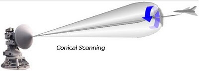
Conical scanning: the target is currently centered on the boresight axis, so it will reflect a signal back to the receiver no matter where the lobe is pointed at that instant (in this case, towards the top). If the target were located slightly above the boresight, a signal would be returned only when the lobe was pointed in that direction. Additionally, since the target is currently located at the edge of the lobe where reception is falling off, when it moves off the boresight the signal will also grow stronger when the lobe is pointed in the right direction.

Straight Flush Radar (1S91)

The Straight Flush was the NATO designation to the Soviet-built 1S91, 25kW G/H band radar, which was part of the 2K12 Kub mobile surface-to-air missile system. Equipped with a continuous wave illuminator and an optical sight, the 1S91 radar had a range of 50 miles (75 km). The Straight Flush radar (1S91) emitted radio waves in the range of radio frequencies from 6 GHz to 8 GHz in the electromagnetic spectrum. This is equal to wave lengths between 5 cm and 3.75 cm. The H band is in the SHF range of the radio spectrum.

The 1S91 mobile radar unit was composed of two radar stations: a target acquisition and distribution radar 1S11 and a continuous wave illuminator 1S31, in addition to an IFF interrogator and an optical channel. While 1S31 antenna was installed on the upper section of the superstructure and the 1S11 on the lower, they could turn around independently.

Thursday, November 4, 2010

SMART-L Radar

The SMART-L is an active phased array radar designed for long-range search according to NATO specifications for a Volume Search Radar. SMART-L stands for Signal Multibeam Acquisition Radar for Tracking, L band. It was developed and manufactured by the firm Hollandse Signaalapparaten (Signaal), now Thales Naval Nederland. It is used on ships by both the German and the Dutch Navy.

The SMART-L is a multibeam radar, which uses 16 antenna elements to simultaneously generate 14 beams by digital beamforming. The beams' vertical directions are controlled electronically, stabilization against the ships movements is also done electronically. Horizontally direction is controlled mechanically by rotating the antenna array. The radar is able to detect targets up to 480km away by a software modification called Extended Long Range (ELR) Mode. With these results the SMART-L radar is one of the most capable long-range radar in the world for detecting tactical as it can be extended to 2000km ballistic missiles.

The SMART-L was designed to fulfil medium range detection of the newest generation of small „stealth” air targets; long range detection of conventional aircraft; guidance support for patrol aircraft; surface surveillance; and high ECCM performance.

Specifications of the SMART-L

Antenna system:

Dimensions; 8.4 × 4 × 4.4 m, 7800 kg
Number of antenna elements: 16 for transmitting and receiving, 8 more for receive only
Number of beams formed: 16
Beamwidth 2.2° horizontal, 10–70° vertical
Polarization: vertical
Frequency: D band (former L band)
Rotational speed: 12 rpm
IFF system integrated, D band

Maximum detection ranges:

Stealth missiles: 85 km
Fighter aircraft: 400 km
Patrol aircraft: 600 km
Maximal numbers of tracked targets:
Airborne: 1000
Seaborne: 100
Radar jamming sources: 32


Wednesday, November 3, 2010

AN/APG-77

The AN/APG-77 is a solid-state, active electronically scanned array radar developed by Northrop Grumman for the US Air Force F-22 aircraft. The AN/APG-77 consists of 1500 transmit\receive modules, each about the size of a gum stick, and can perform a near-instantaneous beam steering in the order of tens of nanoseconds. This advanced radar is fitted out with separate transmitter and receiver for each of the antenna's radiating elements to provide the agility, low radar cross section and wide bandwidth requested for the F/A-22. The APG-77 has a 120° field of view in azimuth and elevation and a power peak of 12kw.

Northrop Grumman have manufactured mor than 100 APG-77 AESA radars, and much of the technology developed for the APG-77 is being used in the APG-81 radar for the F-35 Lightning II. The APG-77 is more reliable, easy to repair, and maintainable than currently fielded aircraft radars through the use of solid state technology and elimination of mechanical moving parts.

The APG-77v1 was installed on F-22 Raptors from Lot 5 and on. This provided full air-to-ground functionality, such as high-resolution synthetic aperture radar mapping, ground moving target indication and track (GMTI/GMTT), automatic cueing and recognition, and combat identification.

Monday, November 1, 2010

SCR-270 Radar

The SCR-270 was the US Army's primary long-range radar throughout World War II. Also known as the Pearl Harbor Radar, the "SCR-270" stood for "Signal Corps Radio model 270". On December 7, 1941, it detected the incoming raid about half an hour before the attack on Pearl Harbor began. Two variants of this radar were developed, the mobile SCR-270, and the fixed SCR-271 which used the same electronics but used an antenna with somewhat greater resolution. An upgraded version, the SCR-289, was also produced, but saw little use. All of the -270 versions were later replaced by newer microwave units after the cavity magnetron was introduced to the US during the Tizard Mission. The only early warning system of the sort to see action was the AN/CPS-1, which was available in late 1944.

The original SCR-270 was composed of a four-truck package. The antenna was mounted on a folding mount derived from a well-drilling derrick, and could be mounted on a flatbed trailer for movement. When opened it was 55 feet (17 m) tall, mounted on an 8-foot (2.4 m) wide base containing motors for rotating the antenna. The antenna itself consisted of a series of 36 half wave dipoles backed with reflectors, arranged in three bays, each bay with twelve dipoles arranged in a three-high four-wide stack. (Later production versions of the SCR-270 used 32 dipoles and reflectors, either eight wide by four high (fixed) or four wide by eight high (mobile)). The antenna mount required another truck (although it had its own wheels and didn't need a trailer), the generator and broadcast amplifier were in another truck, and the operations van was the last.

The antenna of the SCR-270 was swung by command from the operations van, the angle being read by reading numbers painted on the antenna mount. The radar operated at 106 MHz, using a pulse width from 10 to 25 microseconds, and a pulse repetition frequency of 621 Hz. With a wavelength of about nine feet, the SRC-270 was comparable to the contemporary Chain Home system being developed in England, but not to the more advanced microwave systems in Germany. This frequency did turn out to be useful, as it is roughly the size of an airplane's propeller, and provided strong returns from them depending on the angle. Generally it had an operational range of about 150 miles (240 km), and consistently picked up aircraft at that range.