The Magellan XHR is the world's first extreme high resolution scanning electron microscope (SEM). The Magellan XHR model 400L renders unequaled surface-sensitive imaging performance at sub-nanometer resolution, without compromising the analytical capabilities, sample flexibility or ease of use of a traditional analytical SEM. With sub-nm resolution at voltages from 1 to 30 kV, plus a large tiltable stage for 3-D surface imaging of large or multiple samples, this revolutionary new XHR SEM allows the scientist see things he has never seen before.
Sub-nanometer resolution across the 1 to 30kV range has critical value in scientific research and industrial R&D. In addition, it is an absolute requirement in process development, monitoring and control applications in advanced semiconductor manufacturing and the electronics industry. The Magellan XHR SEM family of microscopes extends this capability to applications that were previously impossible or impractical with conventional scanning electron microscopes (SEM), transmission electron microscopes (TEM) or focused ion beam (FIB) systems.
The Magellan Family is available in two models: The Magellan XHR SEM 400, which is optimized for scientific research, and the Magellan™ XHR SEM 400L, engineered for semiconductor labs and other electronics applications. The Magellan XHR SEM 400L comes with an automated loadlock that speeds-up sample throughput, and includes a retractable solid state backscatter electron detector (SSBSED) and S2 compliance kit, all standard equipment. Both models remain highly configurable with more detectors (STEM, EDS and more), a cryostage, specialized holders and many more. An optional full environmental enclosure can be added to isolate the instrument from thermal and acoustic interferences, ensuring peak performance while relaxing site requirements and facility preparation costs.
A transmission electron microscope is a microscope which transmits a beam of electrons through an ultra thin specimen, interacting with the specimen as it passes through. An image is formed from the interaction of the electrons transmitted through the specimen; the image is magnified and focused onto an imaging device, such as a fluorescent screen, on a layer of photographic film, or to be detected by a sensor such as a CCD camera.
Transmission electron microscopes use extremely thin (0.5 µm or less) samples illuminated by the electron beam. Images are recorded by detecting the electrons that pass though the sample to a system of electromagnetic lenses which focus and enlarge the image on the fluorescent screen, photographic film or digital camera. Magnifications beyond 1,000,000x are attainable with a transmission electron microscope.
The scanning electron microscope is a type of electron microscope that images the sample surface by scanning it with a high-energy beam of electrons in a raster scan pattern. Scanning Electron Microscopes (SEM) are used for inspecting topographies of materials with a magnification range that encompasses that of optical microscopy and extends it to the nanoscale. The electrons interact with the atoms that make up the sample producing signals that contain information about the sample's surface topography, composition and other properties such as electrical conductivity. The scanning electron microscope produces different types of signals which include secondary electrons, back-scattered electrons (BSE), characteristic X-rays, light (cathodoluminescence), specimen current and transmitted electrons. These signals result from interactions of the electron beam with atoms at or near the surface of the sample.
Scanning electron microscope micrographs have a large depth of field yielding a characteristic three-dimensional appearance useful for understanding the surface structure of a sample. A wide range of magnifications is possible, from about 10 times (about equivalent to that of a powerful hand-lens) to more than 500,000 times, about 250 times the magnification limit of the best light microscopes.
In a typical Scanning electron microscope (SEM), an electron beam is thermionically emitted from an electron gun fitted with a tungsten filament cathode. Tungsten is normally used in thermionic electron guns because it has the highest melting point and lowest vapour pressure of all metals, thereby allowing it to be heated for electron emission, and because of its low cost. Other types of electron emitters include lanthanum hexaboride (LaB6) cathodes, which can be used in a standard tungsten filament SEM if the vacuum system is upgraded and field emission guns (FEG), which may be of the cold-cathode type using tungsten single crystal emitters or the thermally-assisted Schottky type, using emitters of zirconium oxide.Magellan Scanning Electron Microscope
A petrographic microscope is an optical microscope commonly employed in petrology and optical mineralogy to identify rocks and minerals in thin sections. Petrographic microscopes are built with optical parts that do not add unwanted polarizing effects due to strained glass, or polarization by reflection in prisms and mirrors. These special parts add to the cost and complexity of the microscope. Nevertheless, a "simple polarizing" microscope is easily made by adding inexpensive polarizing filters to a standard biological microscope, often with one in a filter holder beneath the condenser, and a second inserted beneath the head or eyepiece.
The two filters of the petrographic microscope have their polarizing planes oriented perpendicular to one another. When only an isotropic material such as air, water, or glass exists between the filters, all light is blocked. However, most crystalline materials and minerals change the polarizing light directions, which allows some of the altered light to pass through the analyzer to the viewer. Using one polarizer allows for looking at the slide in plane polarized light, while using two allows for analysis under cross polarized light.
A particular light pattern on the upper lens surface of the objectives is created as an conoscopic interference pattern characteristic of uniaxial and biaxial minerals, and produced with convergent polarized light. To observe the interference figure, true petrographic microscopes usually include an accessory called a Bertrand lens, which focuses and enlarges the figure. It is also possible to remove an eyepiece lens to make a direct observation of the objective lens surface.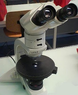
The Celestron biological microscope is a precision optical microscope made of high quality materials designed to be used in biochemical laboratories. It is produced by the American firm Celestron, whose headquarters are in California. The Celestron biological microscope model 44102 consists of three acromatic objectives (4x=40power, 10x=100power, 40x=400power), a plain stage with spring-loaded clips, an arm with an angle choice from 0 to 60º, a focuser with coarse and fine focus knobs and rack and pinion safety stops, a 50mm plano-concave mirror, an eyepiece, a nosepiece, a condenser, and a disc diaphragm with five aperture sizes.
The Celestron microscope has a built-in plano-concave illumination mirror which allows the biochemist to illuminate the specimen from the bottom by reflecting an external light source to the stage. The mirror has a flat side and a concave side. The concave side will concentrate more light onto the specimen than the flat side.
Specifications
-400x Power Biological Microscope
-10x Eyepiece
-4x, 10x, and 40x Objective Lenses
-Fully Coated Glass Optics
-All Metal Body with Monocular Head
-50 mm (2") Mirror Illumination
-Condenser
-5-position Disc Diaphragm
-Powers Available - 40x, 100x, and 400x
-Coarse and Fine Focus Knobs
-Stage with Stage Clips
-Five Prepared Slides
A metallographic microscope is a high power compound microscope with objectives of various magnifications on a turret that rotates them into place. Common magnifications are 100x up to 1000x. It is used for examining the metallic grain structures of heat treated metals as well as studying composite materials. A metallographic microscope is also used in metal foundries for inspection of the cast metal samples. Also known as metallurgical microscope, this type of microscope uses reflecting light that travels through the microscope objective. This is known as epi-illumination. Light in a dissecting stereo microscope is also reflected but it comes from an illumination source from the side, or sometimes is coaxial. In coaxial illumination, the light comes along the same axis as the objective by means of a prism located within the microscope head. Light enters the side of the prism and is reflected downward to the specimen. Still, the light does not travel through the objective as it does in the metallographic microscope.
The Leitz Metalloplan is a largefield metallographic microscope produced by Leitz GmbH in the 1970s. The Metalloplan is equipped with LINNIK interferometry unit that includes 10x and 20x infinity corrected paired optic sets. The Metalloplan stand rests on a four built-in vibration damping special plastic support. The co-axial fine and coarse adjustment acts directly on the object stage. The fine adjustment operates throughout a total travel of 40mm. One interval to the fine adjustment drum corresponds to 1 micron.
The Metalloplan's largefield binocular tube with vertical photo tube is joined to the stand by means of a bayonet lock. It can be rotated through 360º. The mechanical tube length compensator built into the tube maintains simultaneous focusing in the film plane and eyepiece for all interpopullary distances. A beam splitter in the tube directs 80% of the total light into the photo-tube and 20% into the eyepiece tube. The beam splitter of the Metalloplan can be swung out of the optical path so that the full light flux is directed into the eyepiece tubes for observation. The eyepiece tubes were designed to accept largefield eyepieces of 30mm diameter. The 23.2mm diameter Periplan eyepieces can be used with adapters.
The object stage is interchangeable on a dovetail slide and can be lowered considerable for large objects. The co-axial control of the stage must be operated from the right. The vertical illuminator can be intercanged horizontally without the need for lowering the object stage. The light collar between the vertical illuminator and the light aperture in the stand has two filter slots. The standard outfit of the Metalloplan metallographic microscope includes a Lamp Housing 100. Like the Lamp Housing 250, or mirror housing, it is directly joined to the microscope by means of a bayonet lock.

An optical microscope is a high-precision optical instrument which uses a lens or a combination of lenses to produce highly magnified images of small specimens or objects, specially when they are too small to be seen with the naked eye. A light source is used (either by mirrors or lamps) to make it easier to see the subject matter. Microscopy is the use of a microscope or laboratory investigation by a microscope.
There is no one person who invented the microscope as several different inventors experimented with theories and ideas and developed different parts of the concept as they evolved to what is today microscopes. About 1590, two Dutch spectacles makers, Zacharias Janssen and his son Hans, experimented with a crude concept of a microscope which enlarged objects 10x to 30x. In 1609, Galileo improved on the principle of lenses and added a focusing device to improve somewhat on what the Janssens had done previously.
These rudimentary optical instrument did not change much until the 1670s. A Dutchman, Anton Leeuwenhoek, is considered the father of microscope because the advances he made in microscope design and use. He worked as an aprentice in dry goods store where magnifying lenses were used to count the threads in cloth. Anton was inspired by these glasses and taught himself new methods for grinding and polishing small lenses which magnified up to 270x. This led to the first practical microscopes. In 1674, Anton Leeuwenhoek was the first man to see and discribe bacteria, yeast, and plants in a drop of water.
There are two basic configurations of the conventional optical microscope, the simple (one lens) and compound (many lenses). A simple microscope is a microscope that uses only one lens for magnification, and is the original design of optical microscope. Van Leeuwenhoek's microscopes consisted of a small, single converging lens mounted on a brass plate, with a screw mechanism to hold the sample or specimen to be examined. A compound microscope is a microscope which uses multiple lenses to collect light from the sample and then a separate set of lenses to focus the light into the eye or camera. Compound microscopes are heavier, larger and more expensive than simple microscopes due to the increased number of lenses used in construction. The main advantages of multiple lenses are improved numerical aperture, reduced chromatic aberration and exchangeable objective lenses to adjust the magnification.


