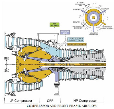
The airflow in the 14-stage high pressure compressor is regulated by variable inlet guide vanes and five stages of variable stator vanes (VSVs). The high pressure compressor compression ratio is approximately 12:1. High pressure compressor discharge and stage 8 bleed air are extracted for emissions control. Compressor discharge air is then directed to the combustor section.
Air entering the combustor is mixed with fuel and ignited. Once combustion becomes self-sustaining, the igniter is de-energized. The combustion gases then exit to the high pressure turbine (HPT). The hot gases from combustion that enters into the high pressure turbine flow out of this to enter the low pressure turbine (LPT), which drives both the low pressure compressor and the output load. The exhaust gases that pass through the low pressure turbine exit through the exhaust duct.
The discharge of the low pressure compressor (LPC) enters into the compressor front frame (CFF). Based on generator loading, the required mass air flow for the high pressure compressor (HPC) varies. At low loads , the low pressure compressor provides excessive airflow which must be vented before entering the high pressure compressor. This is accomplished by the actuation of 12 variable bleed valves (doors) mounted on the external casing of the compressor front frame. The excess air is then vented to the atmosphere through ducting. Primary air from the compressor front frame is then drawn into the high pressure compressor compressed again and distributed to the compressor rear frame.


No comments:
Post a Comment